Capillary Bioreactor V2
Project Summary
This product will be used to reduce VOC concentration in limited air-supply environments.
Project Details
Overview
This project provides STLs and F3D files for the parts of the different versions and forms of the Capillary Bioreactor. This device uses an air-water interface to reduce the concentration of respiratory VOCs. Exhaled VOCs can be detrimental to health of occupants of a space where the air is often re-breathed.
The previous version (V0) of this device operated using glass capillary tubes in a holder. This design was prone to breaking in the capillary column and leaking in the sensor cap as well as along threaded connections. The first failure mode was ameliorated by making a solid plastic capillary column (no need for fragile glass holders). The second by re-dimensioning the sensor ports (as well as adding a little support for the sensors). The final failure was fixed by adding a gasket shelf for o-ring seals.
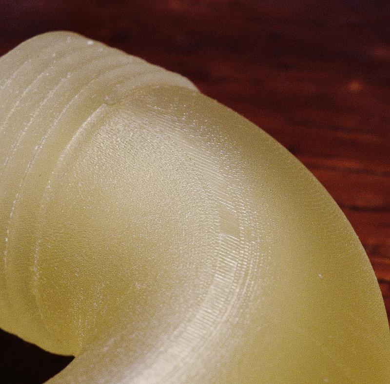
Capillary Bioreactor V1 was printed on the Multijet printer. The UV cure (producing higher resolution) and wax support material (allowing for support removal) of the Multijet were needed to make this design possible. The print quality is sufficient to print capillary channels (1mm diameter x 100mm length) and threads (M25x2, standard tolerances) and retains its water-impermeability.
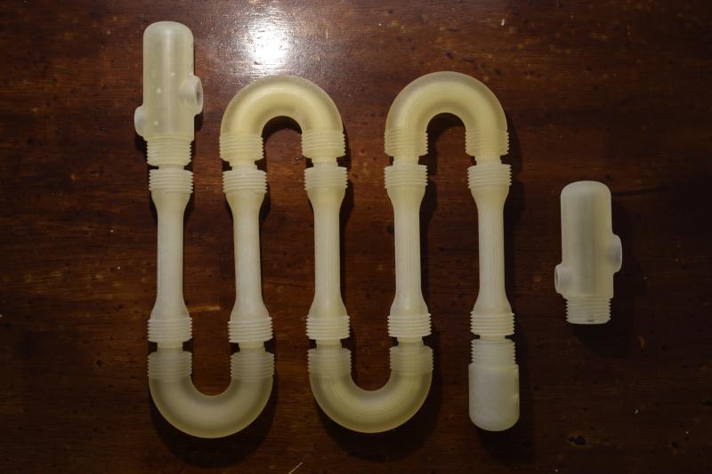
Version 1: Simple Straight (short)
Version 1 improved structurally over Version 0. V1 marks the beginning of this document and the beginning of my (D.M.S.) involvement in the project. Both V0 and V1 are identical in all variables being manipulated in the experiment but V1 provides ease of use and durability. Water is passed through the sensor cap, 100mm of capillary channels (where slug flow is induced), and, eventually, the end cap.
The device is assembled by mounting tubing adapters to all of the ports. This is followed by installation of the o-rings and screwing of the 3 pieces together (with teflon tape). The probes and sensors can then be installed.
The following will be a discussion of the thought process for each of the parts of the first version.
- Sensor Cap
- Water, gas, probe and p.H. inlets
- Saddle joined probe and p.H. stress relief, also adds to water-tightness
- Gasket shelf for 25mm o-ring
- Acts as a combination chamber, allowing for mixing
- Capillary Column (short)
- 25 x 1mm diameter x 100mm length capillary tubes
- Generous fillet to reduce stress concentration around sudden area change
- Thick outer wall to provide rigidity and strength under torsion
- End Cap
- Gas and water outlets
- Gasket shelf for 25mm o-ring
Version 1.1 (long)
Version 1.1 alters one of the experimentation variables: the length of the capillary channel. The channels were elongated from their original 100mm to 200mm. The capillary column is the only part changed in this Capillary Bioreactor. This design has not yet been printed but is on the docket. There is skepticism about clearing the capillary tubes. The wax of the short capillary columns is normally cleared in an oven, post-process. For stubborn wax, the columns are periodically removed from the oven and pressurized air is driven through the capillary tubes, forcing the molten wax out. Even this sometimes leaves some wax which is later removed by a 1mm needle driven through the entire channel lenght.The air-driven removal scales well but 200mm/~8in needles are difficult to find. Solid-core wire is a feasible alternative but its rigidity is left to question and its use is left to experimentation (after printing).
- Capillary Column (short)
- 25 x 1mm diameter x 200mm length capillary tubes
- Generous fillet to reduce stress concentration around sudden area change
- Thick outer wall to provide rigidity and strength under torsion
Version 2: 3 Column Series (hollow)
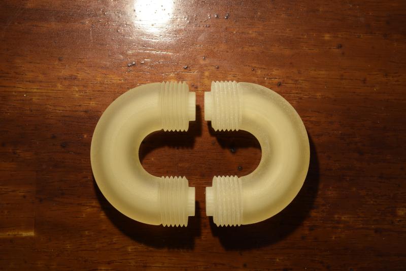
Version 2 alters the same independent variable, the length of the capillary channel, but does so much less ideally. This version features new curved connectors for the capillary columns. Two connectors will be used to connect three short capillary columns together. These five pieces, formed in an 'S', will, in turn, be screwed to the end and sensor caps (☺ pun intended). V2 features hollow curved connectors. This allows for recombination in between capillary columns. This produces many unknown effects that need to be studied to have their impacts understood. There is also a sudden area-change producing head-loss and pressure loss over the system's length. The extent of these effects needs to be determined to asses feasibility and scalability of the prototype system.
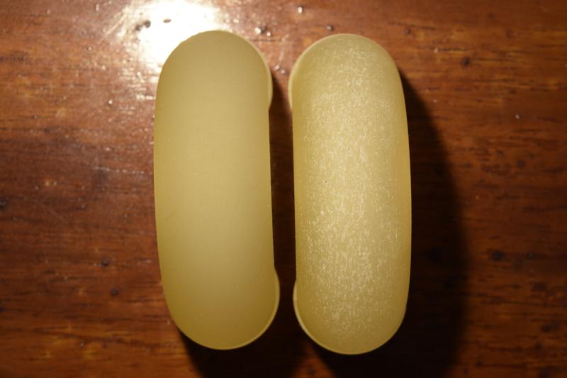
- Curved Connector (hollow)
- 180degree bend
- Gasket shelves
Version 2.1 (capillary)
This version makes altercations on V2. The hollow curved connectors are switched for curved capillary connectors. This reduced the recombination and cross-sectional area change over the flow path. This design provides even more challenges for support removal, pushing the geometric capabilities of the Multijet. Wire and air removal of wax support material will be necessary for the proper functioning of this new part.
- Curved Connector (capillary)
- 180degree bend
- Gasket shelves
- 25 x 1mm diameter, capillary channels
- 5mm x 20mm diameter recombination volume between capillary stages