FlexBeam Assignment
Project Summary
The FlexBeam Assignment is a project completed as part of the EGR121 class. Here you will find detailed drawings and model mockups of the part.
Project Details
Overview
This guide will supply necessary tool suggestions and accompanying jigs that will fit your kit. The purpose of this project is to structure the FlexBeam assignment around digital fabrication technologies and commodity tooling. The documentation is purposely vague as this is a class assignment. There are places you will have to look up information in order to make this.
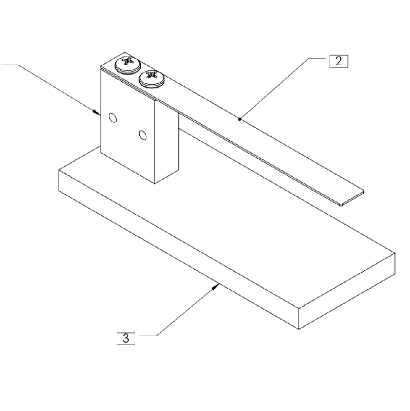
For fabrication purposes, the project is composed of three main components. The beam, the base, and the tower.
Fabricating the Beam
Suggested tool: Waterjet cutter
The beam is a stainless steel component. Stainless steel can be difficult to drill but water jet cutters make short work of it. The challenge is to index the part inside of a machine that can be difficult to perform setups. The best way to achieve this is to simply cut a jig on the tool using any sheet material. TA's have been instructed on how to cut a jig. The part file for the jig is beam_jig.dxf. This step will need to be done each time the jig is removed from the machine. For simplicity, we recommend keeping the jig in place for multiple runs, removing it from the machine will break the indexing. The jig is simply a box cut from any regular stock. The stainless strip that composes the stock for the beam is inserted into the hole and position at the bottom left. Work holding clamps are applied. Care should be taken not to move the jig. Fabricators should then create a DXF file to the specs within the assignment and cut the part out. Make sure to consider your offsets.
Fabricating the Base
Suggested tool: CNC Router
The base is easily fabricated on a CNC router. If carving the base from a kit part already cut to rough dimensions, one can simply use a jig to index the part. Simply fasten a piece of wood or other soft material to the router and cut an L-shape out of it. Take care to dog-bone the corner of the L-shape so it can correctly hold a square shape. A sample jig file is attached to this project that TA's can use. Once the jig is cut, do not remove it from the machine as it will break the indexing. Simply insert the base into the jig and pocket cut the holes out. A second operation can be used with a V-bit to complete the chamfering.
Fabricating the Tower
Suggested tool: CNC Mill
The tower is the most complicated piece of the assembly. The Tormach CNC machine will be the best choice for manufacturing this piece. The tower is made of 3 separate operations. Each operation will need to have the x, y, and z zeroed after each previous operation. Tighten the vice and zero the coordinate system in the top corner that is right-most and closest to the door of the Tormach. The offsets for each drill bit and z-zero tool will be done earlier. The offsets will not need to be redone unless there is concern about slippage. The order in which the operations should be completed is written in the .nc files on the Tormach computer.